
Size of this PNG preview of this SVG file: 289 × 161 pixels. Other resolutions: 320 × 178 pixels | 640 × 357 pixels | 1,024 × 570 pixels | 1,280 × 713 pixels | 2,560 × 1,426 pixels.
Original file (SVG file, nominally 289 × 161 pixels, file size: 22 KB)
Summary
| Description |
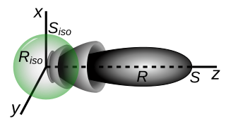
English: Diagram explaining how the directivity (directive gain) of an antenna is defined. R (grey) is the radiation pattern of a typical directive antenna. It radiates most of its power in a narrow lobe oriented along the z axis. Riso shows the radiation pattern of a hypothetical isotropic antenna| that radiates the same total power as the first antenna but radiates it equally in all directions. Isotropic gain G is defined as the ratio of the power density S (in joules per square meter) radiated by the antenna in the direction of its main lobe (here the z-axis) to the power density Giso radiated by the isotropic antenna
|
| Date | |
| Source | Own work |
| Author | Chetvorno |

Licensing
I, the copyright holder of this work, hereby publish it under the following license:
| This file is made available under the Creative Commons CC0 1.0 Universal Public Domain Dedication. | |
| The person who associated a work with this deed has dedicated the work to the public domain by waiving all of their rights to the work worldwide under copyright law, including all related and neighboring rights, to the extent allowed by law. You can copy, modify, distribute and perform the work, even for commercial purposes, all without asking permission.
|
File history
Click on a date/time to view the file as it appeared at that time.
| Date/Time | Thumbnail | Dimensions | User | Comment | |
|---|---|---|---|---|---|
| current | 02:15, 22 June 2021 | | 289 × 161 (22 KB) | Chetvorno | Uploaded own work with UploadWizard |
File usage
The following pages on the English Wikipedia use this file (pages on other projects are not listed):
Global file usage
The following other wikis use this file:
- Usage on fr.wikipedia.org
- Usage on ru.wikipedia.org