69.110.10.76 (talk) →Prevalence: grammar, is -> are |
replaced entire article from http://en.wikipedia.org/w/index.php?title=User:Elcap/Capacitor_Plague&oldid=461764008 |
||
| Line 1: | Line 1: | ||
[[File:Al-Elko-bad-caps-Wiki-07-02-17.jpg|thumb|right| Aluminum electrolytic capacitors with open vents in the can, where the dried electrolyte remains are visible]] |
|||
[[Image:Bad Capacitor 01.jpg|thumbnail|right|Leaking Chhsi capacitors on MSI 694D Pro [[motherboard]]]] |
|||
[[File:Elko-mit-ausgedrücktem-Gummistopfen.jpg|thumb|right| Capacitors with a swollen can and expressed sealing rubber, date of manufacture "0206" (June 2002)]] |
|||
[[File:Blown up electrolytic capacitor.jpg|thumb|right|Detail of a blown up electrolytic capacitor]] |
|||
[[File:Brand_auf_Platine.jpg|thumb|right| Scene of fire on a pc board, caused by leaked electrolyte, which had led to a short circuit between conductors]] |
|||
The '''capacitor plague''' (also known as '''bad capacitors''') is an ongoing problem with premature failure of large numbers of [[electrolytic capacitor]]s of certain brands. Capacitors are used in various electronics equipment, particularly [[motherboard]]s, video cards, [[compact fluorescent lamp]] ballasts, [[LCD]] monitors, and power supplies of [[personal computer]]s. The first flawed capacitors were seen in 1999<!-- badcaps.net -->, but most of the affected capacitors were made in the early to mid 2000s. News of the failures (usually after a few years of use) forced most manufacturers to repair the defects and stop using the capacitors, but some bad capacitors were still being sold or used in equipment {{as of|2007|alt=as of early 2007}}, and faults are still being reported {{As of|2011|lc=on}}.{{Citation needed|date=February 2011}} |
|||
The capacitor plague <ref>Capacitor plague [http://www.bookrags.com/wiki/Capacitor_plague]</ref> (also known as bad capacitors |
|||
<ref>Badcaps.Net, Forum [http://www.badcaps.net/]</ref>) was a problem with a large number of premature failures of aluminium [[electrolytic capacitors]] with non solid or liquid electrolyte of certain brands especially from Taiwan manufacturers <ref>Capacitor plague, identifizierte Hersteller [http://www.opencircuits.com/Capacitor_plague]</ref>. The first flawed capacitors were seen in 1999, but most of the affected capacitors failed in the early to mid 2000s. They failed in various electronics equipment, particularly [[motherboard]]s, video cards, compact [[fluorescent lamp]] ballasts, [[LCD]] monitors, and power supplies of [[personal computer]]s. |
|||
==Cause== |
|||
News of the failures (usually after a few years of use) forced most manufacturers to repair the defects. The problem seems to be ongoing, faults are still being reported as of 2010 <ref>R. Houtman, September 1st, 2010, The capacitor plague strikes again! [http://www.ronhoutman.com/the-capacitor-plague-strikes-again/]</ref>. |
|||
An incorrect [[electrolyte]] formula within a faulty capacitor causes the production of [[hydrogen]] gas (confirmed by [[mass spectrometry]]<ref name=paper>[http://www.dfrsolutions.com/pdfs/2004_Electrolyte_Hillman-Helmold.pdf Identification of Missing or Insufficient Electrolyte Constituents in Failed Aluminium Electrolytic Capacitors; Hilman and Helmold, CARTS 2004]</ref>), leading to bulging or deformation of the capacitor's case, and eventual venting of the electrolyte. The failed capacitors analyzed by two [[University of Maryland]] researchers (by [[ion chromatography]] and mass spectrometry) contained no traces of the [[depolarizer|depolarizing]] agent normally found in such capacitors in order to retain the hydrogen in solution. The root cause of failure for bulging Taiwanese capacitors has been hypothesized to be dissolution of the aluminium into the electrolyte due to poor phosphate-electrolyte balance, rather than the normal evaporation of the electrolyte that all such capacitors undergo. This hypothesis has been confirmed by analyzing the electrolyte using [[energy dispersive X-ray spectroscopy]] (EDS), which confirmed the presence of dissolved aluminium in the Taiwanese capacitors' electrolyte, but not in Japanese ones, and by electrical testing, which confirmed a thinning of the dielectric, because the [[capacitance]] increased before failure, rather than the normal decrease through electrolyte evaporation. The industry standard test failed to capture this behavior, likely because the high voltage used in the test significantly retards the dissolution, whereas it occurs faster at the production environment voltages.<ref name=paper/> |
|||
A serious [[quality control]] problem is that the issue only manifests after use over a period of time; poor quality electrolytic capacitors have the same measurable parameters as good ones when new. Only extensive accelerated life testing with high [[ripple (electrical)|ripple current]]s and high operating temperatures can identify inferior components. After some normal usage, the bad capacitors predictably fail far sooner than normal end-of-life; most electronic components do not systematically fail in this way. |
|||
==Prevalence== |
==Prevalence== |
||
{{Original research|section|date=May 2008}} |
|||
Faulty capacitors have been discovered in motherboards as old as [[Socket 7]] ([[1996]]) and have affected equipment manufactured up to at least 2007. The motherboard companies assembled and sold boards with faulty caps sourced from other manufacturers (see below). Major vendors such as [[Intel]], [[Dell]] and [[HP]] were affected.<ref>[http://asia.cnet.com/reviews/pcperipherals/0,39051168,39289727-2,00.htm PCs plagued by bad capacitors] CNET-Asia.</ref> Circa 2005, Dell spent some US $150 million replacing motherboards entirely and another $150 million on the logistics of determining whether a system is in need of replacement. HP reportedly purged its product line in 2004. The motherboards and power supplies in [[Apple Inc.|Apple]] [[iMac G5]]s<ref>[http://www.apple.com/support/imac/repairextensionprogram/ Apple iMac Repair Extension Program]</ref> and some [[eMac]]s<ref>[http://www.apple.com/support/emac/repairextensionprogram/ Apple eMac Repair Extension Program]</ref> were also affected. |
Faulty capacitors have been discovered in motherboards as old as [[Socket 7]] ([[1996]]) and have affected equipment manufactured up to at least 2007. The motherboard companies assembled and sold boards with faulty caps sourced from other manufacturers (see below). Major vendors such as [[Intel]], [[Dell]] and [[HP]] were affected.<ref>[http://asia.cnet.com/reviews/pcperipherals/0,39051168,39289727-2,00.htm PCs plagued by bad capacitors] CNET-Asia.</ref> Circa 2005, Dell spent some US $150 million replacing motherboards entirely and another $150 million on the logistics of determining whether a system is in need of replacement. HP reportedly purged its product line in 2004. The motherboards and power supplies in [[Apple Inc.|Apple]] [[iMac G5]]s<ref>[http://www.apple.com/support/imac/repairextensionprogram/ Apple iMac Repair Extension Program]</ref> and some [[eMac]]s<ref>[http://www.apple.com/support/emac/repairextensionprogram/ Apple eMac Repair Extension Program]</ref> were also affected. |
||
[[Image:PSU Caps.jpg|left|thumb|250px|A [[power supply unit]] with failed capacitors.]] |
[[Image:PSU Caps.jpg|left|thumb|250px|A [[power supply unit]] with failed capacitors.]] |
||
While capacitor plague largely affects desktop computer hardware, this problem is by no means limited to that area. These capacitors can also be found in |
While capacitor plague largely affects desktop computer hardware, this problem is by no means limited to that area. These capacitors can also be found in power supplies, network switches, audio equipment, [[Flat panel display]]s, and a range of other devices. |
||
Some early brands of [[surface mount]] aluminium electrolytic capacitors suffered from an apparently similar, but actually different, problem involving electrolyte leakage. Surface-mount soldering is usually done by first screen-printing small areas of solder paste onto the [[printed circuit board]], placing the components, and then running the board assembly through a [[reflow oven]] to melt the solder. In an attempt to ensure more reliable soldering, some manufacturers increased the temperature of the reflow, which unknown to them, damages the rubber seals of the capacitors, causing them to dry out or start to leak after one or two years of operation. Compact equipment such as video camcorders are particularly affected by this problem, in most cases needing repair. |
|||
==Symptoms== |
==Symptoms== |
||
[[Image:Buldging tayeh caps 2.jpg|thumbnail|right|Bulging capacitors]] |
[[Image:Buldging tayeh caps 2.jpg|thumbnail|right|Bulging capacitors]] |
||
| Line 26: | Line 19: | ||
*Electrolyte (a crusty brown substance) leaked onto the motherboard from the base of the capacitor or vented from the top, visible as rust-like brown deposits, or a visible hole in the vent. ''The petroleum-based adhesive that is sometimes used to secure the capacitors to the board can be confused with leaked electrolyte; electrolyte is usually wet, adhesive dry. This glue is a thick elastic covering of a sandy yellow colour and darkens (towards black) with heat. A dark brown crust up the side of a capacitor is invariably glue, not electrolyte. The glue is itself sometimes harmful and can corrode leads and tracks covered by it, leading to leakage current or open-circuit; it is not required and can safely be removed. The presence of black glue is a sure sign that the capacitor has overheated due either to internal failure or inadequate ventilation.'' |
*Electrolyte (a crusty brown substance) leaked onto the motherboard from the base of the capacitor or vented from the top, visible as rust-like brown deposits, or a visible hole in the vent. ''The petroleum-based adhesive that is sometimes used to secure the capacitors to the board can be confused with leaked electrolyte; electrolyte is usually wet, adhesive dry. This glue is a thick elastic covering of a sandy yellow colour and darkens (towards black) with heat. A dark brown crust up the side of a capacitor is invariably glue, not electrolyte. The glue is itself sometimes harmful and can corrode leads and tracks covered by it, leading to leakage current or open-circuit; it is not required and can safely be removed. The presence of black glue is a sure sign that the capacitor has overheated due either to internal failure or inadequate ventilation.'' |
||
*High [[equivalent series resistance]] (ESR) can be detected with an [[ESR meter]], but this test sometimes cannot be performed in-circuit without disconnecting the capacitor. Motherboard capacitors are typically in parallel with other capacitors, and cannot be measured individually while in-circuit. However, a high in-circuit ESR reading unequivocally indicates failure of the measured capacitor or capacitors. |
*High [[equivalent series resistance]] (ESR) can be detected with an [[ESR meter]], but this test sometimes cannot be performed in-circuit without disconnecting the capacitor. Motherboard capacitors are typically in parallel with other capacitors, and cannot be measured individually while in-circuit. However, a high in-circuit ESR reading unequivocally indicates failure of the measured capacitor or capacitors. |
||
[[Image:Badcaps-tayeh-4.jpg|thumbnail|right|Failed Tayeh capacitors both of which have vented through their aluminium tops.]] |
|||
[[Image:Badcaps-tayeh-4.jpg|thumbnail|right|Failed Tayeh capacitors both of which have vented through their aluminum tops.]] |
|||
As the capacitor ages, its [[capacitance]] decreases and its ESR increases. When this happens, the capacitors no longer adequately serve their purpose of filtering the [[direct current]] [[voltage]]s on the motherboard, and system instability results. Some common symptoms are: |
As the capacitor ages, its [[capacitance]] decreases and its ESR increases. When this happens, the capacitors no longer adequately serve their purpose of filtering the [[direct current]] [[voltage]]s on the motherboard, and system instability results. Some common symptoms are: |
||
*Not turning on all the time; having to hit reset or try turning the computer on again |
*Not turning on all the time; having to hit reset or try turning the computer on again |
||
| Line 36: | Line 28: | ||
*Failing to complete the [[Power-On Self Test|POST]], or rebooting before it is completed |
*Failing to complete the [[Power-On Self Test|POST]], or rebooting before it is completed |
||
*Never starting the POST; fans spin but the system appears dead |
*Never starting the POST; fans spin but the system appears dead |
||
*Capacitors with high ESR can make power supplies malfunction, sometimes causing further circuit damage. [[CPU core voltage]] or other system voltages may fluctuate or go out of range, possibly with an increase in CPU temperature as the core voltage rises |
*Capacitors with high ESR can make power supplies malfunction, sometimes causing further circuit damage. [[CPU core voltage]] or other system voltages may fluctuate or go out of range, possibly with an increase in CPU temperature as the core voltage rises. |
||
[[Image:vp6 blown capacitor.jpg|thumbnail|left|This failed capacitor has exploded and blown its casing off.]] |
[[Image:vp6 blown capacitor.jpg|thumbnail|left|This failed capacitor has exploded and blown its casing off.]] |
||
[[Image:Blown Power Supply-040610.JPG|thumbnail|right|Failed capacitor from a PC power supply has blown off the board and expelled its contents (foreground: casing on the left, contents of the capacitor on the right.)]] |
[[Image:Blown Power Supply-040610.JPG|thumbnail|right|Failed capacitor from a PC power supply has blown off the board and expelled its contents (foreground: casing on the left, contents of the capacitor on the right.)]] |
||
| Line 42: | Line 34: | ||
Unlike the physical signs which are conclusive evidence the capacitors are failing, many of the operational signs may be caused by other factors, such as a failing [[power supply]], dust clogging a fan, bad [[Random Access Memory|RAM]], or other hardware problems. Instability, once the operating system has loaded, may indicate a software problem (such as some types of [[malware]], poorly-written [[device driver]]s or software), and not a hardware problem at all. If any of these symptoms are experienced, removing the system's case and inspecting the capacitors, especially those around the [[Central processing unit|CPU]], may immediately identify capacitors as the cause. If there are no physical signs, an [[oscilloscope]] may be used to examine the AC [[Ripple (electrical)|ripple voltage]] across capacitors during operation, or an ESR meter to measure ESR when powered down; excessive ripple or ESR is a sign that the capacitors are faulty. |
Unlike the physical signs which are conclusive evidence the capacitors are failing, many of the operational signs may be caused by other factors, such as a failing [[power supply]], dust clogging a fan, bad [[Random Access Memory|RAM]], or other hardware problems. Instability, once the operating system has loaded, may indicate a software problem (such as some types of [[malware]], poorly-written [[device driver]]s or software), and not a hardware problem at all. If any of these symptoms are experienced, removing the system's case and inspecting the capacitors, especially those around the [[Central processing unit|CPU]], may immediately identify capacitors as the cause. If there are no physical signs, an [[oscilloscope]] may be used to examine the AC [[Ripple (electrical)|ripple voltage]] across capacitors during operation, or an ESR meter to measure ESR when powered down; excessive ripple or ESR is a sign that the capacitors are faulty. |
||
==Cause of the failing capacitors== |
== Cause of the failing capacitors - Industrial espionage?== |
||
[[File:Blown up electrolytic capacitor.jpg|thumb|right| Detail of a blown up electrolytic capacitor with dried residuals of the electrolyte]] |
|||
[[Image:DellGX270CounterfeitNichiconCaps1024.jpg|thumbnail|right|Judging by the difference in stencil clarity and μ symbol font between new Nichicon capacitors from a reliable vendor, and bad ones taken from malfunctioning Dell Optiplex GX270 computer, it seems likely the Dell's are counterfeit.{{or|date=September 2011}} Bulging vents and electrolyte leakage can be observed (click on photo to enlarge).]] |
|||
The massive numbers of failures of aluminium electrolytic capacitors with liquid electrolytes, also called “e-caps”, are based on millions of faulty capacitors in the years 1999 to 2007 produced from Taiwanese manufacturers <ref>Low-ESR Aluminium Electrolytic Failures Linked to Taiwanese Raw Material Problems [http://www.molalla.net/members/leeper/alumin~1.pdf]</ref> and failing prematurely after only a few months of operation. Many of the used capacitors had the life time specification (load life) of 2000 h/105 °C. With an average internal temperature of 45 °C on a PC and a ripple current, which corresponds to the data sheet specification, these capacitors have a life expectancy of about 15 years of continuous operation. With respect to this life time expectation a failure after 1.5 to 2 years is really "premature". |
|||
The images of the failures were quite spectacular, bulged or burst cans, expressed sealing rubber and leaking electrolyte were found on countless circuit boards. Many well-known equipment manufacturers such as [[Dell]], [[Cisco]], [[Intel]], [[Asus]] and [[Abit]] had to carry out recalls and repair costs to take account of these capacitors <ref>Heise online, 14.04.2005, Mainboardhersteller steht für Elko-Ausfall gerade, |
|||
[http://www.heise.de/newsticker/meldung/Mainboardhersteller-steht-fuer-Elko-Ausfall-gerade-Update-153175.html]</ref>. Many repair instructions for self-help can be found on the Internet. |
|||
<ref>Explains the basics of replacement capacitor selection and how to replace capacitors [http://www.afrotechmods.com/groovy/capacitor_replacement/capacitor_replacement.htm Capacitor Replacement Video Tutorial in HD]</ref> |
|||
<ref>Repair and bad capacitor information site [http://www.capacitorlab.com/index.htm Capacitor Lab] </ref>. |
|||
As a probable cause of the faulty capacitor-production industrial espionage in connection with the theft of an electrolyte formula <ref>Silicon Chip, 11. May 2003, Motherboard Capacitor Problem Blows Up [http://www.siliconchip.com.au/cms/A_30328/article.html]</ref> is considered. An [[Electrolyte|electrolyte]] developer has probably taken with them, when moving from [[Japan]] to [[Taiwan]], the chemical composition of a new low [[Electrical resistance and conductance|resistance]], inexpensive, [[Water|water]]-containing electrolyte and tried to counterfeit these electrolytes in Taiwan, then to sell it cheaper than the Japanese could. But apparently the formula had been copied incompletely, and it lacked important substances to secure the long-term stability of the capacitors. |
|||
==Development of electrolytic capacitors with water-based electrolytes== |
|||
<gallery caption="Construction of an electrolytic capacitor with non solid electrolyte" class="centered"> |
|||
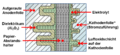
File: Elko-Prinzipschnittbild.png | Cut through the inner construction of an e-cap with the capacitor foils and their surfaces covered with oxide |
|||
File: Elko-Wickelaufbau.png| Picture of the winding of an e-cap |
|||
</gallery> |
|||
The first electrolytic capacitor ever was an [[Aluminium|aluminium]] electrolytic capacitor with a liquid electrolyte, invented by Charles Pollak in January 1896. In principle, the electrolytic capacitors up to this day (2011) remained the same. On an aluminium [[anode]], the [[dielectric]] out of very thin [[aluminium oxide]] layer is raised by formation. The liquid electrolyte adapts the structure of the dielectric, forms the liquid [[cathode]] of the capacitor and thus makes the thin layer thickness of the dielectric effective. A spacer made of paper prevents direct contact of the oxide layer with a second aluminium foil (cathode foil), the electrical connection to the liquid cathode and also saves him. Sealed and provided with connections this construction results in billions of inexpensive and within their lifetime reliable capacitors used for electronic devices. |
|||
The electrolyte as ionic conductor caused most of the ohmic losses in the capacitor. Great efforts have been made over the years to reduce these losses to increase the ripple current, because without such improvements the most important target of development - size reductions - cannot be realized. |
|||
In Japan, in the context of these developments, some manufacturers are busy to develop a new, low-ohmic water-based electrolyte. The conductivity of water-based electrolytes compared to electrolytes with organic [[Solvent|solvents]] like [[gamma-Butyrolactone|GBL]] was significantly improved. Water, with its relatively high [[Permittivity|permittivity]] of ε = 81, is a powerful solvent for electrolytes. As such, it dissolves [[Salt (chemistry)|salts]] in high concentration. The high concentration of dissolved salt [[Ion|ions]] in the electrolyte increases the conductivity. But water will react quite aggressive and violently with unprotected aluminium. It converts aluminium (Al) with a highly exothermic reaction into its [[Hydroxide|hydroxide]] (Al (OH)3). This is accompanied by a strong heat and gas development in the capacitor and may lead to the explosion of the capacitor. Therefore, the main problem in the development of new water-containing electrolytes, is to hinder the aggressiveness of the water against aluminium to get capacitors having a sufficiently good long-term stability. |
|||
The Japanese manufacturer [[Rubycon (company)|Rubycon]] <ref>Rubycon, [http://www.rubycon.co.jp/en/products/]</ref> was the late 1990s, a leader in the development of new water-based electrolyte systems with enhanced conductivity. Rubycon 1998 brought with two series, ZL and ZA, the first capacitors on the market that worked with an electrolyte with a water content of about 40 % and were suitable for a wide temperature range from -40 to +105 °C <ref>Shigeru Uzawa, Akihiko Komatsu, Tetsushi Ogawara, Rubycon Corporation, Ultra Low Impedance Aluminum Electrolytic Capacitor with Water based Electrolyte. [http://sciencelinks.jp/j-east/article/200217/000020021702A0509168.php]</ref>. |
|||
The improvement achieved the conductivity of the electrolyte can be seen by a comparison of two capacitors, both of which have a capacitance of 1000 µF at 16 V nominal voltage with the size DxL = 10x20 mm. The capacitors of the Rubycon YXG series, which are provided with an electrolyte based on an organic solvent can be at an impedance of 46 milliohms loaded with a ripple current of 1400 mA. ZL series capacitors with the new water-based electrolyte can be at an impedance of 23 mΩ charged with the ripple current of 1820 mA , an increase of 30 %. Other manufacturers, such as NCC <ref>NCC, ECC,[http://www.chemi-con.co.jp/e/catalog/aluminum.html]</ref>, Nichicon <ref>Nichicon [http://www.nichicon-us.com/english/products/menu.htm]</ref>, Elna <ref>Elna, [http://www.elna.co.jp/en/capacitor/alumi/index.html]</ref>, follows a short time later. The new series was called "Low ESR" or "Low-impedance", "Ultra-low-impedance" or "High-ripple Current” series in the data sheets. The highly competitive market in the digital data technology and the power supply handle this new development on fast, because by improving the conductivity of the electrolyte could capacitors not only withstand a higher ripple current rating, they were even cheaper, since water is very cheap. Better and even cheaper for high volume products like PCs, LCD screens and power supplies, the cost argument was decisive. |
|||
===Aluminum oxide - solid dielectric and corrosion protection=== |
|||
[[File:REM-Anode-Neu.jpg|thumb|right| SEM image of the rough anode surface of an unused electrolytic capacitor with a view on the openings of the pores in the anode]] |
|||
The electrolyte in an electrolytic capacitor is from an electrical point of view, the actual cathode of the capacitor. But it is on the other side also a chemical, an [[Acid|acid]] or [[Lye|lye]], which must be chemically inert, so that the capacitor, whose inner components are made of aluminium, remains stable over long time. But aluminium is a very reactive, easily oxidised metal. And aqueous acids behave quite aggressively against the aluminium. Only a stable aluminium oxide Al<sub>2</sub>O<sub>3</sub> layer on the surface of the anode and protecting substances known as inhibitors or passivators <ref>J.L. Stevens, T. R. Marshall, A.C. Geiculescu m, C.R. Feger, T.F. Strange, Carts USA 2006, The Effects of Electrolyte Composition on the Deformation Characteristics of Wet Aluminum ICD Capacitors, [http://ecadigitallibrary.com/pdf/CARTS06/5_2zxm.pdf]</ref> in the electrolyte are able to protect aluminium from water-driven corrosive reactions. The problem of water-containing electrolyte systems lies in the control of aggressiveness of the water toward aluminium. |
|||
This problem runs through the development of electrolytic capacitors for over many decades. |
|||
<ref> K. H. Thiesbürger: Der Elektrolyt-Kondensator. 4. Auflage, Page 88 to 91,Roederstein, Landshut 1991<!--Ohne ISBN--> (OCLC 313492506)</ref> |
|||
For even the first technically used electrolytes mid 20th century were mixtures of ethylene glycol and boric acid. But even with these so-called glycol electrolytes do had an unwanted chemical water crystal reaction, according to the scheme: |
|||
From "acid + [[Alcohol|alcohol]]" gets "[[Ester|ester]] + water" |
|||
In a first water-free electrolyte, as the result of esterification a generation of a water content of up to 20 % take place. These electrolytes were originally suitable only for a limited temperature range of -25 to +85 °C. They had a voltage-dependent lifetime, because at higher voltages the leakage current based on the aggressiveness of the water increases exponentially and the associated increased consumption of electrolyte leads to a faster drying out. |
|||
<ref>A. Albertsen, Electrolytic Capacitor Lifetime Estimation [http://jianghai-europe.com/wp-content/uploads/JIANGHAI_Elcap_Lifetime_-_Estimation_AAL.pdf]</ref> |
|||
<ref>Sam G. Parler, Cornell Dubilier, Deriving Life Multipliers for Electrolytic Capacitors |
|||
[http://www.newark.com/pdfs/techarticles/cornell/multipliers.pdf]</ref> |
|||
On the other hand water delivers the oxygen for the self-healing of electrolytic capacitors, the formation of the anode oxide, the dielectric layer of the capacitor. This normal process of formation or self-healing carried out in two reaction steps. First, it transforms with a strongly exothermic reaction aluminium (Al) into its [[Aluminium hydroxide|hydroxide]] Al(OH)<sub>3</sub>: |
|||
'''2Al + 6H<sub>2</sub>O → 2Al(OH)<sub>3</sub> + 3H2 ↑''' |
|||
This reaction is accelerated by a high electric field and by high temperatures and is accompanied by a pressure build up in the capacitor by the released hydrogen gas. The gel-like aluminium hydroxide Al(OH)<sub>3</sub>, even called alumina trihydrate (ATH), aluminic hydroxide, aluminium(III) hydroxide, hydrated alumina converts, in the second reaction step usually slow in a few hours at room temperature, more rapidly in a few minutes at higher temperatures, in the crystalline form of aluminium oxide Al<sub>2</sub>O<sub>3</sub>: |
|||
'''2 Al(OH)<sub>3</sub> → 2 AlO(OH) + 2 H<sub>2</sub>O → Al<sub>2</sub>O<sub>3</sub> + 3 H<sub>2</sub>0''' |
|||
Only the newly formed stable aluminium oxide heal the defects respectively the weak dielectric layer on the anode of the electrolytic capacitor, forms the stable dielectric of the capacitor. It also protects the capacitor from the aggressive reactions of aluminium in the presence of water. However, with the conversion process of the forming or self healing a small amount of water out of the electrolyte will be "consumed". |
|||
===Aluminum hydroxide - loss of self-healing=== |
|||
[[File:REM-Hydroxid-Platten.jpg|thumb|right| SEM image from the anode surface of a failed electrolytic capacitors with grown plaques of aluminium hydroxide]] |
|||
[[File:REM-Hydroxid-Perlen.jpg|thumb|right| SEM image from the anode surface of a failed electrolytic capacitors with grown beads of aluminium hydroxide]] |
|||
The Aluminium oxide layer in the electrolytic capacitor is resistant to chemical attacks, as long as the pH value of the electrolyte is in the range of pH 4.5 to 8.5. <ref>Alu-Lexikon, [http://www.aluinfo.de/index.php/alu-lexikon.html?lid=68]</ref>. However, it should be the pH value of the electrolyte ideally about 7 (neutral). Measurements of leakage current, which were carried out as early as the 1970s have shown that the leakage current was higher, thus chemically induced defects occurred when the pH value deviated from this ideal value |
|||
<ref>J. M. Sanz, J. M. Albella, J. M. Martinez-Duart, ON THE INHIBITION OF THE REAKTION BETWEEN ANODIC ALUMINUM OXIDE AND WATER |
|||
[http://www.deepdyve.com/lp/hindawi-publishing-corporation/on-the-inhibition-of-the-reaction-between-anodic-aluminum-oxide-and-Wn4Q79WyDa]</ref>. |
|||
It is also known that the "normal" course of building the stable aluminium oxide by the formation of aluminium through the intermediate step of the aluminium hydroxide can be interrupted through an alkaline or basic electrolyte. Disruption to the chemistry of this reaction serves as an example the following: |
|||
'''2Al(s) + 2NaOH(aq) + 6H<sub>2</sub>O 2Na+ (aq) + 2[Al(OH)<sub>4</sub>]- + 3H<sub>2</sub>(g)''' |
|||
In this case, it may happen that the hydroxide formed in the first step becomes detached from the aluminum surface and will be NOT transforms in the desired stable form of aluminium oxide. The cause of the healing process building new oxide layer, a defect or a weak dielectric point remains and the defect is not cured. Then there another additional formation of aluminium hydroxide at this point occurs without converting into the stable aluminium oxide. The self-healing inside the e-cap no longer takes place. The reactions do not come to a standstill, the hydroxide in the pores of the anode foil grow and caused by the first step reaction more and more hydrogen gas will be produced in the can increasing the pressure. |
|||
[[File:Elko-Anodenpore-Hydroxidbildung.jpg|400px|center|Attempt at a pictorial representation of the formation of aluminum hydroxide in a pore of a roughened electrolytic capacitor anode foil.]] |
|||
==Wrong electrolyte - The evidence== |
|||
[[File:Elko-Anode-Aluminiumoxid.jpg||thumb|right|Micrograph and EDX analysis correspond to the anode surface of an unused 470 µF-10 V electrolytic capacitor with an intact surface of aluminium oxide, the grooves are marks of the direction of the foil during production (magnification 10x)]] |
|||
[[File:Elko-Anode-Aluminiumhydroxid.jpg|thumb|right|Micrograph and EDX analysis of the anode surface of a failed 470 µF-10 V electrolytic capacitors, the grooves of the marks of the production direction are still visible, but the surface is coated with plate-like aluminium hydroxide (magnification 10x)]] |
|||
<gallery caption="Pictures of an opened failed capacitor " class="centered"> |
|||
File:Elko-Hydroxid-Ausfall-Wickel-geöffnet.jpg | Opened e-cap with extracted winding partly unwinded. The red colored winding is a typical sign of a chemical process in some of the water based electrolytes. |
|||
File: Elko-Hydroxid-Ausfall-Wickel-abgewickelt.jpg| Unwinded winding of a failed e-cap, the foils are glued together, another typical sign of the chemical process in water based electrolytes, no other damages (shorts) are visible |
|||
</gallery> |
|||
This situation of unbraked formation of hydroxide (hydration) and the associated hydrogen gas production was the case to as "capacitor plague" or even "bad caps" mentioned incident with the massive failures of aluminum electrolytic capacitors. It has been demonstrated with the analysis study by two researchers at the [[University of Maryland]] who analyzed the failed capacitors |
|||
<ref name=paper>[http://www.dfrsolutions.com/pdfs/2004_Electrolyte_Hillman-Helmold.pdf Identification of Missing or Insufficient Electrolyte Constituents in Failed Aluminium Electrolytic Capacitors; Hilman and Helmold, CARTS 2004]</ref>). |
|||
These two scientists initially determined by [[ion exchange chromatography]] [[ion chromatography]] and [[mass spectrometry]], that there really is hydrogen gas, which leads to bulging of the capacitor’s case or open the vent. Thus it was proved that the oxidation takes place according to the first step of the formation of alumina. |
|||
Because it has been customary in electrolytic capacitors to bind the hydrogen with the help of reducing or [[depolarizer|depolarizing]] compounds to reduce the resulting pressure then they searched for compounds of this type. Usually aromatic nitro compounds or amines are used in this case. Although the above-mentioned methods are very sensitive to such pressure reducing compounds no traces of the agents was found within the failed capacitors. |
|||
With capacitors, the internal pressure build-up was just so great that the capacitor case was already bulging but the vent had not opened yet, then the pH value of the electrolyte could be identified. The electrolyte of the faulty capacitors was alkaline with pH (7 <pH <8). Comparable Japanese capacitors on the other hand had an electrolyte with a pH in the acidic range (pH ≈ 4). As it is known that aluminium can dissolve in alkaline liquids, but not in acidic media, then with the electrolyte of the faulty capacitors an [[energy dispersive X-ray spectroscopy|EDS-fingerprint analysis]] was made and actually dissolved aluminum could be detected. |
|||
To protect the aluminum against the aggressiveness of the water some phosphate compounds, known as inhibitors or passivators can be used to get long-term stable, capacitors with high aqueous electrolytics. Because phosphate compounds are mentioned in patents regarding to e-caps with aqueous electrolytic systtems. |
|||
<ref> Chang, Jeng-Kuei, Liao, Chi-Min, Chen, Chih-Hsiung, Tsai, Wen-Ta, |
|||
Effect of electrolyte composition on hydration resistance of anodized aluminum oxide |
|||
[http://ir.lib.ncku.edu.tw/handle/987654321/74491]</ref> |
|||
Since in the investigated Taiwanese electrolytes phosphate ions were missing and the electrolyte was also alkaline, so they lacked the protection against water and the more formation of stable alumina oxides was stopped. There only aluminum hydroxide was generated. |
|||
Underlined was the result of chemical analysis by measurement of the electrical capacitance and the leakage current in a long-term test for 56 days. Due to the chemical attack on the oxide layer of these capacitors has been weakened, so that after a short time, the capacitance and the leakage current increased, before both parameters rapidly after opening the vent fell off. |
|||
With the report of Hilmann and Helmond it was proofed that the cause of the failured capacitors actually was a faulty electrolyte used by the Taiwanese manufacturers. It lacked the necessary chemical ingredients to ensure the correct pH of the electrolyte over the time for a long-term stability of the electrolytic capacitors. |
|||
That the electrolyte with its alcaline pH value then had the fatal consequence of continual growth of hydroxide wíthout changing into the stable oxide can be detected on the surface of the anode foil either photographically or with an EDX-fingerprint analysis of the chemical components. |
|||
Even a microscopic image with only a 10-fold magnification, as shown in the pictures right, a significant change in the structure of the anode surface is visible. On the surface of the "fresh" anode from an unused e-cap the strias from the running direction of the anode, resulting in the production process, are clearly visible. The enlargement is however not sufficient to show the openings of the pores in the anode. At the anode, which comes from a failed capacitor out of the Taiwanese production, the surface is overgrown with a placke-like substance transverse to the running direction. An EDX-fingerprint analysis then showed the chemical difference in the surface oxide. The surface of the "fresh" Elko was covered with the stable aluminium oxide. The surface of the failed capacitor was covered with aluminum hydroxide this shows the significantly higher oxygen peak. |
|||
===Electrical effects=== |
|||
[[File:Elko-Reststromverhalten10min.png|thumb|center|Leakage current after a 24 h hot storage test. Capacitors with water based electrolytes have a higher leakage current level than the capacitors with solvent electrolytes based on organic solvents.]] |
|||
[[File:Elko-Anodenfolie-Abformierung.png|thumb|right|Measurement protocol of measurement of the voltage strength of a 10 V anode. The specification was > 14 V, in a failed electrolytic capacitor the voltage strength measured was reduced down to 11.9 V]] |
|||
[[File:Dauerspannungsprüfung-Kap-Verlauf.jpg|thumb|right|An irregular capacitance curve (red), found in a life test, based on starting, water-driven corrosion]] |
|||
A slightly different electrical behavior of almost all electrolytic capacitors with water based electrolytes can be measured against electrolytic capacitors with electrolyte systems based on organic solvents. The turn-on leakage current after storage times is at a higher level. However, if a water based electrolyte is still in stable condition, ie not yet fallen into the alkaline pH range, then the leakage current is adjusted after a few minutes on a low value. The defects that had been formed by the aggressive behavior of water on aluminum are healed quickly. But if the electrolyte during the operation time has drifted into the alkaline range, then the process of self-healing will end after the formation of aluminum hydroxide. The subsequent conversion into the stable aluminium oxide is prevented by the alkaline environment. The defects that cause the leakage current remains, covered only by hydroxide, and can get further be attacked from the water. |
|||
The dielectric voltage strength of the hydroxide only can reach the height of the operating voltage applied, which is usually lower than the rated voltage. This decreased dielectric voltage strength of the anode can be measured. Pictured right, such a measurement result is shown. The reduced dielectric voltage strength compared to the original anode voltage strength shows that a chemical process has sustained damaged the oxide layer of the anode. |
|||
Through this damage the thickness of the insulating dielectric layer gets smaller. That means, according to the formula of the plate capacitor, |
|||
<math>C=\varepsilon \cdot { {A} \over {d} }</math> |
|||
with the permittivity “ε”, the electrode surface “A” and the distance between the electrodes to each other “d”, that with thinner dielectric the capacitance value increases. And indeed, electrolytic capacitors at the beginning of the fatal continual growth of hydroxide, shows a little bulging of the can but not yet open the vent an increased capacitance value can be measured, such as the red colored capacitance curve in a life test in the picture above right shows. |
|||
The final stage of this process is reached when the hydrogen gas generated by the constant continual growth of aluminium hydroxide is increased to so such high pressure that the vent gets open or the sealing rubber will be pressed out. Simply said, the capacitor bursts. If the capacitor then is open, it dries out very quickly loses its capacitance down to a minimum value and the ESR increases significantly up to the kΩ range. Because the ripple current still flows over the capacitors ESR, the heat losses grows on, increases the temperature of the winding up to an overheat situation and color the paper of the winding into clearly brown. |
|||
==E-cap failures after 2007 – why?== |
|||
[[File:Hydroxid-Ausfall-V9A-P1010951-1.JPG|thumb|right|Burst capacitor with the date code V9A, (production date September 2007), failed after about 2.5 years of operation]] |
|||
[[File:REM und EDX-Al-Oxid.jpg|thumb|right|SEM image and EDX fingerprint analysis of the surface of a "fresh" anode out of a 1000 uF - 10 V electrolytic capacitor, the pore openings in the anode are clearly visible, the surface is covered with aluminum oxide.]] |
|||
[[File:REM und EDX-Al-Hydroxid.jpg|thumb|right|SEM image and EDX fingerprint analysis of the surface of an anode out of a failed 1000 uF - 10 V electrolytic capacitor. The aluminium hydroxide a has overgrown all structures on the anode. The failure occurred at the end of the calculated lifetime]] |
|||
The first press releases about the massive problem with a large number of premature failures in Taiwanese electrolytic capacitors appeared in September 2002. It can be assumed that by mid-2003 the concerned producers have changed the production and used a "true" composite electrolyte. With a decreased life time of about 1.5 to 3 years for the failing capacitors from mid-2003 on therefore up to mid-2006, the last of the bad capacitors should be failed. The Internet often called the year 2007 as the end point of failures with bad capacitors. |
|||
After this date actually no more incidents should occur. But even after the year 2007, the year in which the failure of Taiwan bad capacitors with the wrong electrolyte should really be over, the messages with failed capacitors are available on the Internet.<ref>Am I afflicted by the Capacitor Plague? (got photos), 03-16-2010, |
|||
[http://www.tomshardware.co.uk/forum/271884-12-afflicted-capacitor-plague-photos]</ref>. |
|||
The problem of bursting electrolytic capacitors still exist, the images of failed capacitors described the identical effects with open vents and outpressed rubber. Affected by these failures are capacitor series for rated voltages from 6.3 V to 100 V, which have one thing in common, they have a water based electrolyte with a high water content of up to 75%. In the catalogs of the manufacturers, they are characterized by the catchword "Low-ESR" capacitors or “Low-impedance ", "Ulta-Low-impedance" or "High-ripple-current” capacitors. These capacitors must not be confused with aluminum-polymer capacitors, which are often called "low-ESR” electrolytic capacitors. The failures affects only aluminium electrolytic capacitors with non solid electrolyte. |
|||
If now failures occur in the above-described type of capacitors with a newer production date than 2007, so it can not be justified by the incomplete electrolyte of former Taiwanese production. If in an SEM and EDX analysis of the failed capacitors aluminium hydroxide is still detected, not necessarily the electrolyte is faulty because it also can be that the circuit have been wrong designed. Therefore, two questions must be answered first: |
|||
*1) Was the ripple current and temperature stress on the capacitors correct? |
|||
*2) Did the failure occur prematurely, before or after the end of life time? |
|||
It should be noted that the commonly used 10-degree rule (Arrhenius rule, RGT-rule) to estimate the capacitors life time (10 °C reduction in temperature doubles the life time) for the electrolytic capacitors with water based electrolytes often is not valid. The 10-degree rule applies only when it is confirmed by the respective capacitor manufacturer, see <ref>Panasonic (10-Grad-Regel) [http://www.industrial.panasonic.com/www-data/pdf/ABA0000/ABA0000TE6.pdf]</ref> <ref>NIC Life expectancy of aluminum electrolytic capacitors (rev.1)[http://www.niccomp.com/Products/General/Alumlyticlifeexpect.pdf]</ref>. |
|||
Because some manufacturers specify different life calculation formulas, sometimes even different formulas for their various series |
|||
<ref>NCC Technical Note, Cat. No. 1001L [http://www.chemi-con.co.jp/e/catalog/pdf/al-e/al-sepa-e/001-guide/al-technote-e-110701.pdf]</ref>. Even though a graphical method is specified to estimate the lifetime of a capacitor by a manufacturer and it seems that the curves follows the 10-degree-law, one should not be fooled. The slope of the specified curve in this example is different than under the 10-degree rule <ref>Samwha, ALUMINUM ELECTROLYTIC CAPACITORS, General introduction, Expected life chart, Seite 14, [http://2.imimg.com/data2/LJ/XP/MY-3485198/electrolyc-capacitors.pdf]</ref> |
|||
The following two examples of e-cap-life calculations show the difference in results between the 10-degree rule and the formula that the manufacturer Rubycon has specified for their water based electrolyte Series ZL.<ref>Rubycon, LIFE OF ALUMINUM ELECTROLYTIC CAPACITORS, Page 9, equation 4.7 [http://www.rubycon.co.jp/en/products/alumi/pdf/Life.pdf]</ref>. |
|||
For a PC power supply a capacitor with the lifetime specification of 1000 h/105 C ° is selected. The average operating temperature of the capacitor, measured in the metallic region near the vent is 45 °C. The ripple current load in the first example corresponds to the specified data sheet value (100%). This gives a lifetime of |
|||
*10-degree rule: 64,000 h, 7.3 years |
|||
*Rubycon formula: 64,000 h, 7.3 years |
|||
For the second example the double data sheet value of the ripple current is obtained. This gives a lifetime of |
|||
*10-degree rule: 22.600 h, 2.6 years |
|||
*Rubycon formula: 6000 h, 0.7 years |
|||
The calculated lifetime at twice the value of the ripple current following the formula from Rubycon is significantly smaller than after the 10-degree rule. This reflects the fact that the operation of capacitors with water based electrolytes at ripple current overload can be problematic. This is also reflected in a disclaimer of many capacitor manufacturers, in which the operation is warned with a higher ripple current than the specified value: |
|||
*''Do not apply a ripple current exceeding the rated maximum ripple current''. |
|||
The difference in shortening the lifetime of electrolytic capacitors at higher loads comparing e-caps with water based electrolytes with those with electrolytes based on organic solvents is to find in the aggressiveness of the water against the aluminum. Capacitors with solvent electrolytes such as [[GBL]] have a significantly better leakage current behavior than those with water based electrolytes. |
|||
<ref>TDK-EPC, Langzeitstabilität von Alu-Elkos, Rasten ohne Folgen, Juli 2007[http://www.epcos.de/web/generator/Web/Sections/Components/Page,locale=nn,r=247996,a=490592,principals=none_21none_21_20_21_20_21_20.html]</ref> <ref>Jens Both, Stromsparer, Reststromverhalten moderner Elektrolytkondensatoren |
|||
[http://www.tadiranbatteries.de/deu/downloads/both_deu.pdf]</ref>. |
|||
Thus, in operation consumes lesser electrolyte which has a positive impact on the life time. Water-containing capacitors then because of the higher leakage current consume more electrolyte, whereby the life of the capacitors is reduced. |
|||
Measurement protocol of measuring the dielectric strength of a cathode out of a failed 10 V electrolytic capacitor, the specification was about 1.5 V, the measured voltage strength was 2.9 V. |
|||
On the other hand, a high ripple current load can also result in a consumption of electrolyte, especially during discharging the capacitor. This is based on a physical effect that can sometimes lead to a forming process of the cathode foil in the capacitor. Normally the cathode foil is covered with an oxide layer that is formed by contact with the air in a natural way on the aluminum surface. This oxide layer has a voltage strength at room temperature of about 1 up to 1.5 V. At 105 °C decreases the voltage strength down to about 0.7 to 1.2 V. |
|||
[[File:KATHODEN-Formierung.png|thumb|center|During discharging an electrolytic capacitor the polarity of the capacitor reverses, the voltage distribution over the internal resistances reverses and builds up a voltage of opposite polarity to the cathode foil which at higher ripple current loads may build up an additional oxide layer on the cathode foil]] |
|||
Now, if a charged capacitor will be discharged during the discharging parts of the ripple current, then the polarity of the capacitor reverses: The cathode becomes an anode, the current flows out of the capacitor. Than the voltage distribution over the internal resistances builds up a voltage of opposite polarity to the cathode foil. The natural voltage strength of the cathode oxide now can withstand the discharging loads up to the specified value in the relevant data sheet if the electrolytic capacitor has a correct design. The capacitor has a correct construction when the cathode capacitance CK is very large compared to the anode capacitance CA. This is usually given when the cathode capacitance is factor of 10 larger than the anode capacitance <ref> K. H. Thiesbürger: Der Elektrolyt-Kondensator. 4. Auflage, Page 71 to 77, Roederstein, Landshut 1991<!--Without ISBN--> (OCLC 313492506)</ref>. Increasing the ripple current load over the specified value, especially when the temperature is high, however, may generate a reverse voltage to the cathode foil higher than the natural voltage strength and may be form up the oxide on the cathode foil. To form a thicker oxide layer on the cathode foil is associated with the loss of electrolyte which reduces the life time of the capacitor. |
|||
[[File:Blown capacitor on video card.jpg|thumb|right|A blown capacitor on a PCB is only evidence of a "bad" one with wrong electrolyte, if it can be shown that the capacitor has failed "prematurely"]] |
|||
The lifetime of the electrolytic capacitors with high water content in the electrolyte is thus determined not only by the operating temperature and the aligned gradual evaporation of the electrolyte, but also by the leakage current and a possible forming process of the cathode foil at high ripple current load. All parameters, the evaporation of electrolytes, the higher leakage current for capacitors with water based electrolytes and, if it is applied, a high ripple current, are consuming fluid electrolytes. From a certain point the up to the saturation limit dissolved salts in the electrolyte will crystallize. The electrolyte changes, initially the conductivity of the electrolyte decreases, the ESR increases. The change of the electrolyte for some product lines also may have an influence to the pH, the pH may change as stronger as closer he gets to the end of the service life of electrolytic capacitors. Gets then the pH of the electrolyte at the end of life in the alkaline region, which is found often in capacitors with water based electrolytes, then stops, as described above, the regeneration of the defects and the fatal, unrestrained growth of aluminum hydroxide begins. If this behavior now comes together with the end of their calculated life and the electrolytic capacitors bursts, then it looks as if a new case of the "capacitor plague" occurred. |
|||
The failure pictures, burst e-cap, expressed sealing rubber, leaked electrolyte are identical to those of the production with the "wrong" electrolyte. If now with capacitors build after the year 2007, failures of this kind occur, it only can be determined by a careful recalculation of the entire circuit with all load conditions for the capacitor, such as temperature and ripple current load, whether it's a bug in the capacitor or an error in the design of the circuit. |
|||
Because only when the capacitor failed prematurely, before it reach the end of his life, may be assumed that it has a faulty electrolyte or another failure mode. That might be also the reason for the court between a well-known manufacturer of computer hardware with a capacitor manufacturer, as can be seen advertised in the "Techreport".<ref>Cyril Kowaliski, Court documents suggest Dell mishandled capacitor plague, June 29, 2010[http://techreport.com/discussions.x/19178]</ref> |
|||
An incorrect calculation of the service life time and a faulty electrolyte results in the same failure pictures. |
|||
In one case, the reason for the manufacture of faulty electrolytic capacitors was [[industrial espionage]] gone wrong: several [[Taiwan]]ese electrolyte manufacturers began using a stolen formula that was incomplete, and lacked ingredients needed to produce a stable capacitor.<ref name="Feb2003Spectrum">{{cite journal |
|||
However, a burst of an electrolytic capacitor, even if it has reached its end of life, is an extraordinary process. Until now, could be assumed that electrolytic capacitors are drying out over the time, but also in the dry state showed no visible irregularities. It seems that water based electrolytes in e-caps of some manufacturers have a different behavior at the end of their life: they burst! Analysing the prematurely burst capacitor it not can be determined whether thermal or electrical overload has led to the opening of the vent or if the failure is based on a faulty electrolyte. For a correct assessment of new failures with e-caps, it is therefore absolutely necessary to determine the exact operating conditions and to calculate the service a life according to the manufacturer's specification. |
|||
| last = Chiu |
|||
| first = Yu-Tzu |
|||
| coauthors = Samuel K. Moore |
|||
| title = Faults & Failures: Leaking capacitors muck up motherboards |
|||
| journal = [[IEEE Spectrum]] |
|||
| volume = 40 |
|||
| issue = 2 |
|||
| month = February |
|||
| year = 2003 |
|||
| pages = 16–17 |
|||
| issn = 0018-9235 |
|||
| doi = 10.1109/MSPEC.2003.1176509 |
|||
| url = http://spectrum.ieee.org/computing/hardware/leaking-capacitors-muck-up-motherboards |
|||
| accessdate = 2008-03-10 |
|||
}}</ref> |
|||
===Note, date of manufacture code=== |
|||
When a faulty capacitor is charged, the [[water]]-based [[electrolyte]] becomes unstable and breaks down, producing [[hydrogen]] gas. Since these types of capacitors are sealed in an [[aluminium]] casing, the pressure builds up within the capacitor until either the flat metal top of the capacitor begins to bend, or the rubber sealing plug is pushed down. Eventually the pressure exceeds the strength of the metal casing and venting occurs, either by blowing out the rubber bottom of the capacitor, or bursting the scored metal vent on the top of the capacitor. When an [[electrolytic capacitor]] bursts, effects can range from a pop and a hissing noise to a small explosion. Venting is typically messy, and the corrosive electrolyte must be cleaned off the circuit board to prevent further damage. |
|||
Many manufacturers use an 2-digit abbreviation according to IEC 60062 standard to code the date of production (date code) of electrolytic capacitors |
|||
*First digit: Year of production, S = 2004, T = 2005, U = 2006, V = 2007, W = 2008, X = 2009, A = 2010, B = 2011 |
|||
*Second digit: Month of production, 1 to 9 = Jan. to Sept., O = Oct., N = Nov., D = Dec. |
|||
Example: X8 = August 2009 |
|||
[[IEEE Spectrum]] covered the issue,<ref name="Feb2003Spectrum" /> and later estimated that the problem cost {{nowrap|US $100 million }} to fix.<ref>{{cite journal |
|||
| last = Pecht |
|||
| first = Michael |
|||
| coauthors = Sanjay Tiku |
|||
| title = Bogus! Electronic manufacturing and consumers confront a rising tide of counterfeit electronics |
|||
| url = http://spectrum.ieee.org/computing/hardware/bogus |
|||
| journal = [[IEEE Spectrum]] |
|||
| month = May |
|||
| year = 2006 |
|||
| issn = 0018-9235 |
|||
| volume = 43 |
|||
| issue = 5 |
|||
| pages = 37–46 |
|||
| doi = 10.1109/MSPEC.2006.1628506 |
|||
}} [http://web.archive.org/web/20060716183827/http://spectrum.ieee.org/may06/3423 archive.org copy]</ref> |
|||
==See also== |
==See also== |
||
Revision as of 00:10, 23 November 2011


The capacitor plague [1] (also known as bad capacitors [2]) was a problem with a large number of premature failures of aluminium electrolytic capacitors with non solid or liquid electrolyte of certain brands especially from Taiwan manufacturers [3]. The first flawed capacitors were seen in 1999, but most of the affected capacitors failed in the early to mid 2000s. They failed in various electronics equipment, particularly motherboards, video cards, compact fluorescent lamp ballasts, LCD monitors, and power supplies of personal computers. News of the failures (usually after a few years of use) forced most manufacturers to repair the defects. The problem seems to be ongoing, faults are still being reported as of 2010 [4].
Prevalence
Faulty capacitors have been discovered in motherboards as old as Socket 7 (1996) and have affected equipment manufactured up to at least 2007. The motherboard companies assembled and sold boards with faulty caps sourced from other manufacturers (see below). Major vendors such as Intel, Dell and HP were affected.[5] Circa 2005, Dell spent some US $150 million replacing motherboards entirely and another $150 million on the logistics of determining whether a system is in need of replacement. HP reportedly purged its product line in 2004. The motherboards and power supplies in Apple iMac G5s[6] and some eMacs[7] were also affected.

While capacitor plague largely affects desktop computer hardware, this problem is by no means limited to that area. These capacitors can also be found in power supplies, network switches, audio equipment, Flat panel displays, and a range of other devices.
Symptoms


The most common method of identifying capacitors which have failed because of bad electrolyte is visual inspection. The capacitance may degrade to 4% of the original value, as opposed to an expected 50% capacity degradation over the lifetime.[8] Such a capacitor will show one or more of these symptoms:
- Bulging of the vent on the top of the capacitor. (The "vent" is the impression stamped in the top of the can. The impression forms the seams of the vent. It is designed so that if the capacitor becomes pressurized it will split at the vent's seams relieving the pressure rather than exploding.)
- Sitting crooked on the circuit board as the bottom rubber plug is pushed out
- Electrolyte (a crusty brown substance) leaked onto the motherboard from the base of the capacitor or vented from the top, visible as rust-like brown deposits, or a visible hole in the vent. The petroleum-based adhesive that is sometimes used to secure the capacitors to the board can be confused with leaked electrolyte; electrolyte is usually wet, adhesive dry. This glue is a thick elastic covering of a sandy yellow colour and darkens (towards black) with heat. A dark brown crust up the side of a capacitor is invariably glue, not electrolyte. The glue is itself sometimes harmful and can corrode leads and tracks covered by it, leading to leakage current or open-circuit; it is not required and can safely be removed. The presence of black glue is a sure sign that the capacitor has overheated due either to internal failure or inadequate ventilation.
- High equivalent series resistance (ESR) can be detected with an ESR meter, but this test sometimes cannot be performed in-circuit without disconnecting the capacitor. Motherboard capacitors are typically in parallel with other capacitors, and cannot be measured individually while in-circuit. However, a high in-circuit ESR reading unequivocally indicates failure of the measured capacitor or capacitors.

As the capacitor ages, its capacitance decreases and its ESR increases. When this happens, the capacitors no longer adequately serve their purpose of filtering the direct current voltages on the motherboard, and system instability results. Some common symptoms are:
- Not turning on all the time; having to hit reset or try turning the computer on again
- Instabilities (hangs, BSODs, kernel panics, etc.), especially when symptoms get progressively more frequent over time
- Memory errors, especially ones that get more frequent with time
- Spontaneous reboots
- In case of on-board video cards, unstable image in some video modes
- Failing to complete the POST, or rebooting before it is completed
- Never starting the POST; fans spin but the system appears dead
- Capacitors with high ESR can make power supplies malfunction, sometimes causing further circuit damage. CPU core voltage or other system voltages may fluctuate or go out of range, possibly with an increase in CPU temperature as the core voltage rises.


Unlike the physical signs which are conclusive evidence the capacitors are failing, many of the operational signs may be caused by other factors, such as a failing power supply, dust clogging a fan, bad RAM, or other hardware problems. Instability, once the operating system has loaded, may indicate a software problem (such as some types of malware, poorly-written device drivers or software), and not a hardware problem at all. If any of these symptoms are experienced, removing the system's case and inspecting the capacitors, especially those around the CPU, may immediately identify capacitors as the cause. If there are no physical signs, an oscilloscope may be used to examine the AC ripple voltage across capacitors during operation, or an ESR meter to measure ESR when powered down; excessive ripple or ESR is a sign that the capacitors are faulty.
Cause of the failing capacitors - Industrial espionage?

The massive numbers of failures of aluminium electrolytic capacitors with liquid electrolytes, also called “e-caps”, are based on millions of faulty capacitors in the years 1999 to 2007 produced from Taiwanese manufacturers [9] and failing prematurely after only a few months of operation. Many of the used capacitors had the life time specification (load life) of 2000 h/105 °C. With an average internal temperature of 45 °C on a PC and a ripple current, which corresponds to the data sheet specification, these capacitors have a life expectancy of about 15 years of continuous operation. With respect to this life time expectation a failure after 1.5 to 2 years is really "premature".
The images of the failures were quite spectacular, bulged or burst cans, expressed sealing rubber and leaking electrolyte were found on countless circuit boards. Many well-known equipment manufacturers such as Dell, Cisco, Intel, Asus and Abit had to carry out recalls and repair costs to take account of these capacitors [10]. Many repair instructions for self-help can be found on the Internet. [11] [12].
As a probable cause of the faulty capacitor-production industrial espionage in connection with the theft of an electrolyte formula [13] is considered. An electrolyte developer has probably taken with them, when moving from Japan to Taiwan, the chemical composition of a new low resistance, inexpensive, water-containing electrolyte and tried to counterfeit these electrolytes in Taiwan, then to sell it cheaper than the Japanese could. But apparently the formula had been copied incompletely, and it lacked important substances to secure the long-term stability of the capacitors.
Development of electrolytic capacitors with water-based electrolytes
- Construction of an electrolytic capacitor with non solid electrolyte
-
 Cut through the inner construction of an e-cap with the capacitor foils and their surfaces covered with oxide
 -
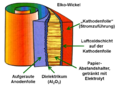 Picture of the winding of an e-cap


The first electrolytic capacitor ever was an aluminium electrolytic capacitor with a liquid electrolyte, invented by Charles Pollak in January 1896. In principle, the electrolytic capacitors up to this day (2011) remained the same. On an aluminium anode, the dielectric out of very thin aluminium oxide layer is raised by formation. The liquid electrolyte adapts the structure of the dielectric, forms the liquid cathode of the capacitor and thus makes the thin layer thickness of the dielectric effective. A spacer made of paper prevents direct contact of the oxide layer with a second aluminium foil (cathode foil), the electrical connection to the liquid cathode and also saves him. Sealed and provided with connections this construction results in billions of inexpensive and within their lifetime reliable capacitors used for electronic devices. The electrolyte as ionic conductor caused most of the ohmic losses in the capacitor. Great efforts have been made over the years to reduce these losses to increase the ripple current, because without such improvements the most important target of development - size reductions - cannot be realized.
In Japan, in the context of these developments, some manufacturers are busy to develop a new, low-ohmic water-based electrolyte. The conductivity of water-based electrolytes compared to electrolytes with organic solvents like GBL was significantly improved. Water, with its relatively high permittivity of ε = 81, is a powerful solvent for electrolytes. As such, it dissolves salts in high concentration. The high concentration of dissolved salt ions in the electrolyte increases the conductivity. But water will react quite aggressive and violently with unprotected aluminium. It converts aluminium (Al) with a highly exothermic reaction into its hydroxide (Al (OH)3). This is accompanied by a strong heat and gas development in the capacitor and may lead to the explosion of the capacitor. Therefore, the main problem in the development of new water-containing electrolytes, is to hinder the aggressiveness of the water against aluminium to get capacitors having a sufficiently good long-term stability.
The Japanese manufacturer Rubycon [14] was the late 1990s, a leader in the development of new water-based electrolyte systems with enhanced conductivity. Rubycon 1998 brought with two series, ZL and ZA, the first capacitors on the market that worked with an electrolyte with a water content of about 40 % and were suitable for a wide temperature range from -40 to +105 °C [15].
The improvement achieved the conductivity of the electrolyte can be seen by a comparison of two capacitors, both of which have a capacitance of 1000 µF at 16 V nominal voltage with the size DxL = 10x20 mm. The capacitors of the Rubycon YXG series, which are provided with an electrolyte based on an organic solvent can be at an impedance of 46 milliohms loaded with a ripple current of 1400 mA. ZL series capacitors with the new water-based electrolyte can be at an impedance of 23 mΩ charged with the ripple current of 1820 mA , an increase of 30 %. Other manufacturers, such as NCC [16], Nichicon [17], Elna [18], follows a short time later. The new series was called "Low ESR" or "Low-impedance", "Ultra-low-impedance" or "High-ripple Current” series in the data sheets. The highly competitive market in the digital data technology and the power supply handle this new development on fast, because by improving the conductivity of the electrolyte could capacitors not only withstand a higher ripple current rating, they were even cheaper, since water is very cheap. Better and even cheaper for high volume products like PCs, LCD screens and power supplies, the cost argument was decisive.
Aluminum oxide - solid dielectric and corrosion protection

The electrolyte in an electrolytic capacitor is from an electrical point of view, the actual cathode of the capacitor. But it is on the other side also a chemical, an acid or lye, which must be chemically inert, so that the capacitor, whose inner components are made of aluminium, remains stable over long time. But aluminium is a very reactive, easily oxidised metal. And aqueous acids behave quite aggressively against the aluminium. Only a stable aluminium oxide Al2O3 layer on the surface of the anode and protecting substances known as inhibitors or passivators [19] in the electrolyte are able to protect aluminium from water-driven corrosive reactions. The problem of water-containing electrolyte systems lies in the control of aggressiveness of the water toward aluminium.
This problem runs through the development of electrolytic capacitors for over many decades. [20] For even the first technically used electrolytes mid 20th century were mixtures of ethylene glycol and boric acid. But even with these so-called glycol electrolytes do had an unwanted chemical water crystal reaction, according to the scheme: From "acid + alcohol" gets "ester + water" In a first water-free electrolyte, as the result of esterification a generation of a water content of up to 20 % take place. These electrolytes were originally suitable only for a limited temperature range of -25 to +85 °C. They had a voltage-dependent lifetime, because at higher voltages the leakage current based on the aggressiveness of the water increases exponentially and the associated increased consumption of electrolyte leads to a faster drying out. [21]
On the other hand water delivers the oxygen for the self-healing of electrolytic capacitors, the formation of the anode oxide, the dielectric layer of the capacitor. This normal process of formation or self-healing carried out in two reaction steps. First, it transforms with a strongly exothermic reaction aluminium (Al) into its hydroxide Al(OH)3:
2Al + 6H2O → 2Al(OH)3 + 3H2 ↑
This reaction is accelerated by a high electric field and by high temperatures and is accompanied by a pressure build up in the capacitor by the released hydrogen gas. The gel-like aluminium hydroxide Al(OH)3, even called alumina trihydrate (ATH), aluminic hydroxide, aluminium(III) hydroxide, hydrated alumina converts, in the second reaction step usually slow in a few hours at room temperature, more rapidly in a few minutes at higher temperatures, in the crystalline form of aluminium oxide Al2O3:
2 Al(OH)3 → 2 AlO(OH) + 2 H2O → Al2O3 + 3 H20
Only the newly formed stable aluminium oxide heal the defects respectively the weak dielectric layer on the anode of the electrolytic capacitor, forms the stable dielectric of the capacitor. It also protects the capacitor from the aggressive reactions of aluminium in the presence of water. However, with the conversion process of the forming or self healing a small amount of water out of the electrolyte will be "consumed".
Aluminum hydroxide - loss of self-healing


The Aluminium oxide layer in the electrolytic capacitor is resistant to chemical attacks, as long as the pH value of the electrolyte is in the range of pH 4.5 to 8.5. [23]. However, it should be the pH value of the electrolyte ideally about 7 (neutral). Measurements of leakage current, which were carried out as early as the 1970s have shown that the leakage current was higher, thus chemically induced defects occurred when the pH value deviated from this ideal value [24]. It is also known that the "normal" course of building the stable aluminium oxide by the formation of aluminium through the intermediate step of the aluminium hydroxide can be interrupted through an alkaline or basic electrolyte. Disruption to the chemistry of this reaction serves as an example the following:
2Al(s) + 2NaOH(aq) + 6H2O 2Na+ (aq) + 2[Al(OH)4]- + 3H2(g)
In this case, it may happen that the hydroxide formed in the first step becomes detached from the aluminum surface and will be NOT transforms in the desired stable form of aluminium oxide. The cause of the healing process building new oxide layer, a defect or a weak dielectric point remains and the defect is not cured. Then there another additional formation of aluminium hydroxide at this point occurs without converting into the stable aluminium oxide. The self-healing inside the e-cap no longer takes place. The reactions do not come to a standstill, the hydroxide in the pores of the anode foil grow and caused by the first step reaction more and more hydrogen gas will be produced in the can increasing the pressure.

Wrong electrolyte - The evidence


- Pictures of an opened failed capacitor
-
 Opened e-cap with extracted winding partly unwinded. The red colored winding is a typical sign of a chemical process in some of the water based electrolytes.
 -
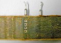 Unwinded winding of a failed e-cap, the foils are glued together, another typical sign of the chemical process in water based electrolytes, no other damages (shorts) are visible


This situation of unbraked formation of hydroxide (hydration) and the associated hydrogen gas production was the case to as "capacitor plague" or even "bad caps" mentioned incident with the massive failures of aluminum electrolytic capacitors. It has been demonstrated with the analysis study by two researchers at the University of Maryland who analyzed the failed capacitors [25]). These two scientists initially determined by ion exchange chromatography ion chromatography and mass spectrometry, that there really is hydrogen gas, which leads to bulging of the capacitor’s case or open the vent. Thus it was proved that the oxidation takes place according to the first step of the formation of alumina.
Because it has been customary in electrolytic capacitors to bind the hydrogen with the help of reducing or depolarizing compounds to reduce the resulting pressure then they searched for compounds of this type. Usually aromatic nitro compounds or amines are used in this case. Although the above-mentioned methods are very sensitive to such pressure reducing compounds no traces of the agents was found within the failed capacitors.
With capacitors, the internal pressure build-up was just so great that the capacitor case was already bulging but the vent had not opened yet, then the pH value of the electrolyte could be identified. The electrolyte of the faulty capacitors was alkaline with pH (7 <pH <8). Comparable Japanese capacitors on the other hand had an electrolyte with a pH in the acidic range (pH ≈ 4). As it is known that aluminium can dissolve in alkaline liquids, but not in acidic media, then with the electrolyte of the faulty capacitors an EDS-fingerprint analysis was made and actually dissolved aluminum could be detected. To protect the aluminum against the aggressiveness of the water some phosphate compounds, known as inhibitors or passivators can be used to get long-term stable, capacitors with high aqueous electrolytics. Because phosphate compounds are mentioned in patents regarding to e-caps with aqueous electrolytic systtems. [26] Since in the investigated Taiwanese electrolytes phosphate ions were missing and the electrolyte was also alkaline, so they lacked the protection against water and the more formation of stable alumina oxides was stopped. There only aluminum hydroxide was generated.
Underlined was the result of chemical analysis by measurement of the electrical capacitance and the leakage current in a long-term test for 56 days. Due to the chemical attack on the oxide layer of these capacitors has been weakened, so that after a short time, the capacitance and the leakage current increased, before both parameters rapidly after opening the vent fell off. With the report of Hilmann and Helmond it was proofed that the cause of the failured capacitors actually was a faulty electrolyte used by the Taiwanese manufacturers. It lacked the necessary chemical ingredients to ensure the correct pH of the electrolyte over the time for a long-term stability of the electrolytic capacitors. That the electrolyte with its alcaline pH value then had the fatal consequence of continual growth of hydroxide wíthout changing into the stable oxide can be detected on the surface of the anode foil either photographically or with an EDX-fingerprint analysis of the chemical components.
Even a microscopic image with only a 10-fold magnification, as shown in the pictures right, a significant change in the structure of the anode surface is visible. On the surface of the "fresh" anode from an unused e-cap the strias from the running direction of the anode, resulting in the production process, are clearly visible. The enlargement is however not sufficient to show the openings of the pores in the anode. At the anode, which comes from a failed capacitor out of the Taiwanese production, the surface is overgrown with a placke-like substance transverse to the running direction. An EDX-fingerprint analysis then showed the chemical difference in the surface oxide. The surface of the "fresh" Elko was covered with the stable aluminium oxide. The surface of the failed capacitor was covered with aluminum hydroxide this shows the significantly higher oxygen peak.
Electrical effects


A slightly different electrical behavior of almost all electrolytic capacitors with water based electrolytes can be measured against electrolytic capacitors with electrolyte systems based on organic solvents. The turn-on leakage current after storage times is at a higher level. However, if a water based electrolyte is still in stable condition, ie not yet fallen into the alkaline pH range, then the leakage current is adjusted after a few minutes on a low value. The defects that had been formed by the aggressive behavior of water on aluminum are healed quickly. But if the electrolyte during the operation time has drifted into the alkaline range, then the process of self-healing will end after the formation of aluminum hydroxide. The subsequent conversion into the stable aluminium oxide is prevented by the alkaline environment. The defects that cause the leakage current remains, covered only by hydroxide, and can get further be attacked from the water.
The dielectric voltage strength of the hydroxide only can reach the height of the operating voltage applied, which is usually lower than the rated voltage. This decreased dielectric voltage strength of the anode can be measured. Pictured right, such a measurement result is shown. The reduced dielectric voltage strength compared to the original anode voltage strength shows that a chemical process has sustained damaged the oxide layer of the anode. Through this damage the thickness of the insulating dielectric layer gets smaller. That means, according to the formula of the plate capacitor,

with the permittivity “ε”, the electrode surface “A” and the distance between the electrodes to each other “d”, that with thinner dielectric the capacitance value increases. And indeed, electrolytic capacitors at the beginning of the fatal continual growth of hydroxide, shows a little bulging of the can but not yet open the vent an increased capacitance value can be measured, such as the red colored capacitance curve in a life test in the picture above right shows. The final stage of this process is reached when the hydrogen gas generated by the constant continual growth of aluminium hydroxide is increased to so such high pressure that the vent gets open or the sealing rubber will be pressed out. Simply said, the capacitor bursts. If the capacitor then is open, it dries out very quickly loses its capacitance down to a minimum value and the ESR increases significantly up to the kΩ range. Because the ripple current still flows over the capacitors ESR, the heat losses grows on, increases the temperature of the winding up to an overheat situation and color the paper of the winding into clearly brown.
E-cap failures after 2007 – why?


The first press releases about the massive problem with a large number of premature failures in Taiwanese electrolytic capacitors appeared in September 2002. It can be assumed that by mid-2003 the concerned producers have changed the production and used a "true" composite electrolyte. With a decreased life time of about 1.5 to 3 years for the failing capacitors from mid-2003 on therefore up to mid-2006, the last of the bad capacitors should be failed. The Internet often called the year 2007 as the end point of failures with bad capacitors.
After this date actually no more incidents should occur. But even after the year 2007, the year in which the failure of Taiwan bad capacitors with the wrong electrolyte should really be over, the messages with failed capacitors are available on the Internet.[27].
The problem of bursting electrolytic capacitors still exist, the images of failed capacitors described the identical effects with open vents and outpressed rubber. Affected by these failures are capacitor series for rated voltages from 6.3 V to 100 V, which have one thing in common, they have a water based electrolyte with a high water content of up to 75%. In the catalogs of the manufacturers, they are characterized by the catchword "Low-ESR" capacitors or “Low-impedance ", "Ulta-Low-impedance" or "High-ripple-current” capacitors. These capacitors must not be confused with aluminum-polymer capacitors, which are often called "low-ESR” electrolytic capacitors. The failures affects only aluminium electrolytic capacitors with non solid electrolyte. If now failures occur in the above-described type of capacitors with a newer production date than 2007, so it can not be justified by the incomplete electrolyte of former Taiwanese production. If in an SEM and EDX analysis of the failed capacitors aluminium hydroxide is still detected, not necessarily the electrolyte is faulty because it also can be that the circuit have been wrong designed. Therefore, two questions must be answered first:
- 1) Was the ripple current and temperature stress on the capacitors correct?
- 2) Did the failure occur prematurely, before or after the end of life time?
It should be noted that the commonly used 10-degree rule (Arrhenius rule, RGT-rule) to estimate the capacitors life time (10 °C reduction in temperature doubles the life time) for the electrolytic capacitors with water based electrolytes often is not valid. The 10-degree rule applies only when it is confirmed by the respective capacitor manufacturer, see [28] [29].
Because some manufacturers specify different life calculation formulas, sometimes even different formulas for their various series [30]. Even though a graphical method is specified to estimate the lifetime of a capacitor by a manufacturer and it seems that the curves follows the 10-degree-law, one should not be fooled. The slope of the specified curve in this example is different than under the 10-degree rule [31]
The following two examples of e-cap-life calculations show the difference in results between the 10-degree rule and the formula that the manufacturer Rubycon has specified for their water based electrolyte Series ZL.[32].
For a PC power supply a capacitor with the lifetime specification of 1000 h/105 C ° is selected. The average operating temperature of the capacitor, measured in the metallic region near the vent is 45 °C. The ripple current load in the first example corresponds to the specified data sheet value (100%). This gives a lifetime of
- 10-degree rule: 64,000 h, 7.3 years
- Rubycon formula: 64,000 h, 7.3 years
For the second example the double data sheet value of the ripple current is obtained. This gives a lifetime of
- 10-degree rule: 22.600 h, 2.6 years
- Rubycon formula: 6000 h, 0.7 years
The calculated lifetime at twice the value of the ripple current following the formula from Rubycon is significantly smaller than after the 10-degree rule. This reflects the fact that the operation of capacitors with water based electrolytes at ripple current overload can be problematic. This is also reflected in a disclaimer of many capacitor manufacturers, in which the operation is warned with a higher ripple current than the specified value:
- Do not apply a ripple current exceeding the rated maximum ripple current.
The difference in shortening the lifetime of electrolytic capacitors at higher loads comparing e-caps with water based electrolytes with those with electrolytes based on organic solvents is to find in the aggressiveness of the water against the aluminum. Capacitors with solvent electrolytes such as GBL have a significantly better leakage current behavior than those with water based electrolytes. [33] [34].
Thus, in operation consumes lesser electrolyte which has a positive impact on the life time. Water-containing capacitors then because of the higher leakage current consume more electrolyte, whereby the life of the capacitors is reduced. Measurement protocol of measuring the dielectric strength of a cathode out of a failed 10 V electrolytic capacitor, the specification was about 1.5 V, the measured voltage strength was 2.9 V.
On the other hand, a high ripple current load can also result in a consumption of electrolyte, especially during discharging the capacitor. This is based on a physical effect that can sometimes lead to a forming process of the cathode foil in the capacitor. Normally the cathode foil is covered with an oxide layer that is formed by contact with the air in a natural way on the aluminum surface. This oxide layer has a voltage strength at room temperature of about 1 up to 1.5 V. At 105 °C decreases the voltage strength down to about 0.7 to 1.2 V.

Now, if a charged capacitor will be discharged during the discharging parts of the ripple current, then the polarity of the capacitor reverses: The cathode becomes an anode, the current flows out of the capacitor. Than the voltage distribution over the internal resistances builds up a voltage of opposite polarity to the cathode foil. The natural voltage strength of the cathode oxide now can withstand the discharging loads up to the specified value in the relevant data sheet if the electrolytic capacitor has a correct design. The capacitor has a correct construction when the cathode capacitance CK is very large compared to the anode capacitance CA. This is usually given when the cathode capacitance is factor of 10 larger than the anode capacitance [35]. Increasing the ripple current load over the specified value, especially when the temperature is high, however, may generate a reverse voltage to the cathode foil higher than the natural voltage strength and may be form up the oxide on the cathode foil. To form a thicker oxide layer on the cathode foil is associated with the loss of electrolyte which reduces the life time of the capacitor.

The lifetime of the electrolytic capacitors with high water content in the electrolyte is thus determined not only by the operating temperature and the aligned gradual evaporation of the electrolyte, but also by the leakage current and a possible forming process of the cathode foil at high ripple current load. All parameters, the evaporation of electrolytes, the higher leakage current for capacitors with water based electrolytes and, if it is applied, a high ripple current, are consuming fluid electrolytes. From a certain point the up to the saturation limit dissolved salts in the electrolyte will crystallize. The electrolyte changes, initially the conductivity of the electrolyte decreases, the ESR increases. The change of the electrolyte for some product lines also may have an influence to the pH, the pH may change as stronger as closer he gets to the end of the service life of electrolytic capacitors. Gets then the pH of the electrolyte at the end of life in the alkaline region, which is found often in capacitors with water based electrolytes, then stops, as described above, the regeneration of the defects and the fatal, unrestrained growth of aluminum hydroxide begins. If this behavior now comes together with the end of their calculated life and the electrolytic capacitors bursts, then it looks as if a new case of the "capacitor plague" occurred.
The failure pictures, burst e-cap, expressed sealing rubber, leaked electrolyte are identical to those of the production with the "wrong" electrolyte. If now with capacitors build after the year 2007, failures of this kind occur, it only can be determined by a careful recalculation of the entire circuit with all load conditions for the capacitor, such as temperature and ripple current load, whether it's a bug in the capacitor or an error in the design of the circuit.
Because only when the capacitor failed prematurely, before it reach the end of his life, may be assumed that it has a faulty electrolyte or another failure mode. That might be also the reason for the court between a well-known manufacturer of computer hardware with a capacitor manufacturer, as can be seen advertised in the "Techreport".[36]
An incorrect calculation of the service life time and a faulty electrolyte results in the same failure pictures. However, a burst of an electrolytic capacitor, even if it has reached its end of life, is an extraordinary process. Until now, could be assumed that electrolytic capacitors are drying out over the time, but also in the dry state showed no visible irregularities. It seems that water based electrolytes in e-caps of some manufacturers have a different behavior at the end of their life: they burst! Analysing the prematurely burst capacitor it not can be determined whether thermal or electrical overload has led to the opening of the vent or if the failure is based on a faulty electrolyte. For a correct assessment of new failures with e-caps, it is therefore absolutely necessary to determine the exact operating conditions and to calculate the service a life according to the manufacturer's specification.
Note, date of manufacture code
Many manufacturers use an 2-digit abbreviation according to IEC 60062 standard to code the date of production (date code) of electrolytic capacitors
- First digit: Year of production, S = 2004, T = 2005, U = 2006, V = 2007, W = 2008, X = 2009, A = 2010, B = 2011
- Second digit: Month of production, 1 to 9 = Jan. to Sept., O = Oct., N = Nov., D = Dec.
Example: X8 = August 2009
See also
References
- ^ Capacitor plague [1]
- ^ Badcaps.Net, Forum [2]
- ^ Capacitor plague, identifizierte Hersteller [3]
- ^ R. Houtman, September 1st, 2010, The capacitor plague strikes again! [4]
- ^ PCs plagued by bad capacitors CNET-Asia.
- ^ Apple iMac Repair Extension Program
- ^ Apple eMac Repair Extension Program
- ^ "Bad Capacitors: Information and symptoms". 100211 lowyat.net
- ^ Low-ESR Aluminium Electrolytic Failures Linked to Taiwanese Raw Material Problems [5]
- ^ Heise online, 14.04.2005, Mainboardhersteller steht für Elko-Ausfall gerade, [6]
- ^ Explains the basics of replacement capacitor selection and how to replace capacitors Capacitor Replacement Video Tutorial in HD
- ^ Repair and bad capacitor information site Capacitor Lab
- ^ Silicon Chip, 11. May 2003, Motherboard Capacitor Problem Blows Up [7]
- ^ Rubycon, [8]
- ^ Shigeru Uzawa, Akihiko Komatsu, Tetsushi Ogawara, Rubycon Corporation, Ultra Low Impedance Aluminum Electrolytic Capacitor with Water based Electrolyte. [9]
- ^ NCC, ECC,[10]
- ^ Nichicon [11]
- ^ Elna, [12]
- ^ J.L. Stevens, T. R. Marshall, A.C. Geiculescu m, C.R. Feger, T.F. Strange, Carts USA 2006, The Effects of Electrolyte Composition on the Deformation Characteristics of Wet Aluminum ICD Capacitors, [13]
- ^ K. H. Thiesbürger: Der Elektrolyt-Kondensator. 4. Auflage, Page 88 to 91,Roederstein, Landshut 1991 (OCLC 313492506)
- ^ A. Albertsen, Electrolytic Capacitor Lifetime Estimation [14]
- ^ Sam G. Parler, Cornell Dubilier, Deriving Life Multipliers for Electrolytic Capacitors [15]
- ^ Alu-Lexikon, [16]
- ^ J. M. Sanz, J. M. Albella, J. M. Martinez-Duart, ON THE INHIBITION OF THE REAKTION BETWEEN ANODIC ALUMINUM OXIDE AND WATER [17]
- ^ Identification of Missing or Insufficient Electrolyte Constituents in Failed Aluminium Electrolytic Capacitors; Hilman and Helmold, CARTS 2004
- ^ Chang, Jeng-Kuei, Liao, Chi-Min, Chen, Chih-Hsiung, Tsai, Wen-Ta, Effect of electrolyte composition on hydration resistance of anodized aluminum oxide [18]
- ^ Am I afflicted by the Capacitor Plague? (got photos), 03-16-2010, [19]
- ^ Panasonic (10-Grad-Regel) [20]
- ^ NIC Life expectancy of aluminum electrolytic capacitors (rev.1)[21]
- ^ NCC Technical Note, Cat. No. 1001L [22]
- ^ Samwha, ALUMINUM ELECTROLYTIC CAPACITORS, General introduction, Expected life chart, Seite 14, [23]
- ^ Rubycon, LIFE OF ALUMINUM ELECTROLYTIC CAPACITORS, Page 9, equation 4.7 [24]
- ^ TDK-EPC, Langzeitstabilität von Alu-Elkos, Rasten ohne Folgen, Juli 2007[25]
- ^ Jens Both, Stromsparer, Reststromverhalten moderner Elektrolytkondensatoren [26]
- ^ K. H. Thiesbürger: Der Elektrolyt-Kondensator. 4. Auflage, Page 71 to 77, Roederstein, Landshut 1991 (OCLC 313492506)
- ^ Cyril Kowaliski, Court documents suggest Dell mishandled capacitor plague, June 29, 2010[27]
External links
- Capacitor Replacement Video Tutorial in HD - Explains the basics of replacement capacitor selection and how to replace capacitors
- Capacitor Lab - Repair and bad capacitor information site
- Motherboard Capacitor Problem Blows Up — An article about capacitor failures